P-10 · SEE 324
Modelled a Plate Exchanger for 1 MW of Cooling
I studied the area and pumping tradeoff for a 1 MW plate exchanger using a simplified model built from catalogue data.
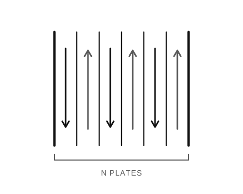
The problem
This course project followed the warm glycol loop from my data-centre cooling study. The aim was to pass 1 MW from glycol leaving the servers at 55 °C to cold water entering at 5 °C. I started with the dimensions and rating of a 20-plate catalogue exchanger, treated its passages as smooth slots, and compared three water outlet temperatures.
What the model showed
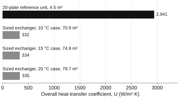
The 20-plate unit moved about 584 kW in the 15 °C outlet case, short of the 1 MW duty. Scaling the smooth-slot calculation for the full load gave roughly 71 to 80 m² of area. In the 20-plate reference unit, lower water flow reduced calculated pumping power; the separate sizing calculation needed more area. I reported the middle case, about 75 m², as a balance. It was a result of that model, not a selected piece of equipment.
Where it fell short
At 75 m², the same plate size implies roughly 300 plates. Flow slows in each passage, and the smooth-slot calculation becomes laminar. A later check of the report inputs shows that the calculated heat-transfer coefficient barely changes across the three water flows. The pumping figures, meanwhile, came from the 20-plate unit. They cannot be paired with the scaled area's pressure drop to choose a real exchanger.
I would model plate count and flow per passage together, using correlations for the actual corrugated plates and checking the result against manufacturer data. This project got me interested in how heat transfer and pumping cost push against each other.